
- All
- Product Name
- Product Keyword
- Product Model
- Product Summary
- Product Description
- Multi Field Search
Views: 0 Author: Site Editor Publish Time: 2026-10-28 Origin: Site


Aeration accounts for 50–60% of a wastewater treatment plant’s energy consumption. Manual airflow adjustments inevitably force operators into a difficult balancing act. Guesswork leads to energy-wasting over-aeration or compliance-risking under-aeration. You cannot rely on fixed-speed systems to handle dynamic biological loads efficiently.
Stricter effluent limits and rising operational costs push plant managers toward smarter solutions. Facilities must evaluate automated, data-driven airflow management. Modifying operations based on real-time data is no longer optional. It is a strict regulatory and financial necessity.
Implementing a Dissolved Oxygen (DO) feedback control loop solves this operational dilemma. We will explore how automated systems dynamically scale output to match exact biological demand. You will discover how this methodology perfectly bridges the gap between process biology and mechanical efficiency. By the end of this guide, you will understand how to optimize treatment quality while drastically cutting power usage.
DO feedback loops shift aeration control from predictive guesswork to real-time biological demand, reducing energy consumption by 20–40%.
The effectiveness of the control loop depends heavily on the turndown capability and response time of the chosen wastewater aeration blower.
Centrifugal blowers, particularly the high-speed centrifugal blower, offer the optimal combination of variable-speed efficiency and rapid responsiveness required for precise DO tracking.
Successful implementation requires mitigating sensor latency and properly tuning PID controllers to prevent mechanical wear from system "hunting."
Wastewater treatment facilities face intense pressure to meet strict discharge permits. Simultaneously, they must manage escalating electricity costs. Balancing these two priorities requires moving away from outdated operational models.
Static aeration represents the historical standard for many municipal and industrial plants. Operators run fixed-speed continuous equipment based on peak historical loads. They build in a massive safety factor. If the worst-case scenario requires 1,000 cubic feet per minute, they deliver 1,000 cubic feet per minute around the clock.
The financial cost of this static approach is staggering. Biological demand naturally fluctuates throughout the day. Morning peak flows bring heavy organic loads. Nighttime lulls see minimal biological activity. Pumping maximum air during low-demand hours wastes immense electricity. Furthermore, over-aerating can shear bacterial floc. This degrades settling in the secondary clarifiers. You pay a high price for a compromised process.
Upgrading to a dynamic system requires clear benchmarks. You must define what success looks like before installing new hardware. Facilities typically measure automation success through three specific criteria.
Maintaining DO setpoints: Typical biological processes require 1.5–2.0 mg/L of dissolved oxygen. A successful system holds this setpoint with minimal deviation, regardless of influent flow rate.
Measurable energy reduction: We track efficiency by measuring kilowatts consumed per pound of BOD or Ammonia removed. Automation should drive this metric down significantly.
Elimination of compliance breaches: Sudden biological load spikes often overwhelm static systems. Dynamic automation ramps up air instantly. This prevents dangerous drops in oxygen and protects effluent quality.
Facility managers often hesitate at the initial capital expenditure. Buying DO probes, programmable logic controllers (PLCs), and variable-frequency drives (VFDs) requires funding. However, the return on investment moves quickly.
Automated control typically pays for itself within 24 to 36 months. You achieve this through immediate operational expenditure reductions. Energy bills drop drastically when you stop aerating empty basins. Additionally, many utility companies offer generous energy rebates for installing VFD-compatible equipment. These incentives further accelerate the payback period.
A closed-loop system requires several components working in perfect harmony. You cannot optimize biology without a reliable mechanical and electronic chain of command.
The process begins in the aeration basin. Optical or galvanic DO probes continuously measure oxygen concentrations. We strongly favor optical sensors in modern applications. They use luminescent technology rather than chemical reactions. This makes them highly resistant to interference from complex wastewater matrices.
These sensors gather real-time data every few seconds. They act as the eyes of the operation. Accurate data acquisition prevents the entire system from acting on false premises.
The PLC serves as the central brain. It receives raw oxygen data from the probes. The PLC utilizes a PID (Proportional-Integral-Derivative) algorithm to process this information. It constantly calculates the error between the current DO reading and your target setpoint.
The algorithm predicts how aggressively the system must react. A large gap triggers a strong response. A minor deviation triggers a gentle adjustment. Proper signal processing prevents overreaction.
Once the PLC calculates the necessary adjustment, it sends a command. This command travels as a 4-20mA analog signal or via digital industrial protocols. The Variable Frequency Drive receives this signal.
The VFD acts as the translator between software and hardware. It alters the electrical frequency supplied to the motor. It tells the motor exactly how fast it needs to spin to meet the current demand.
The physical work happens at the machine level. The VFD modulates the motor speed of the wastewater aeration blower. The machine physically speeds up or slows down.
This action precisely increases or decreases the mass flow of air delivered to the diffusers. The diffusers then release microscopic bubbles into the mixed liquor. The bacteria consume the oxygen. The sensor reads the new level. The loop begins again.
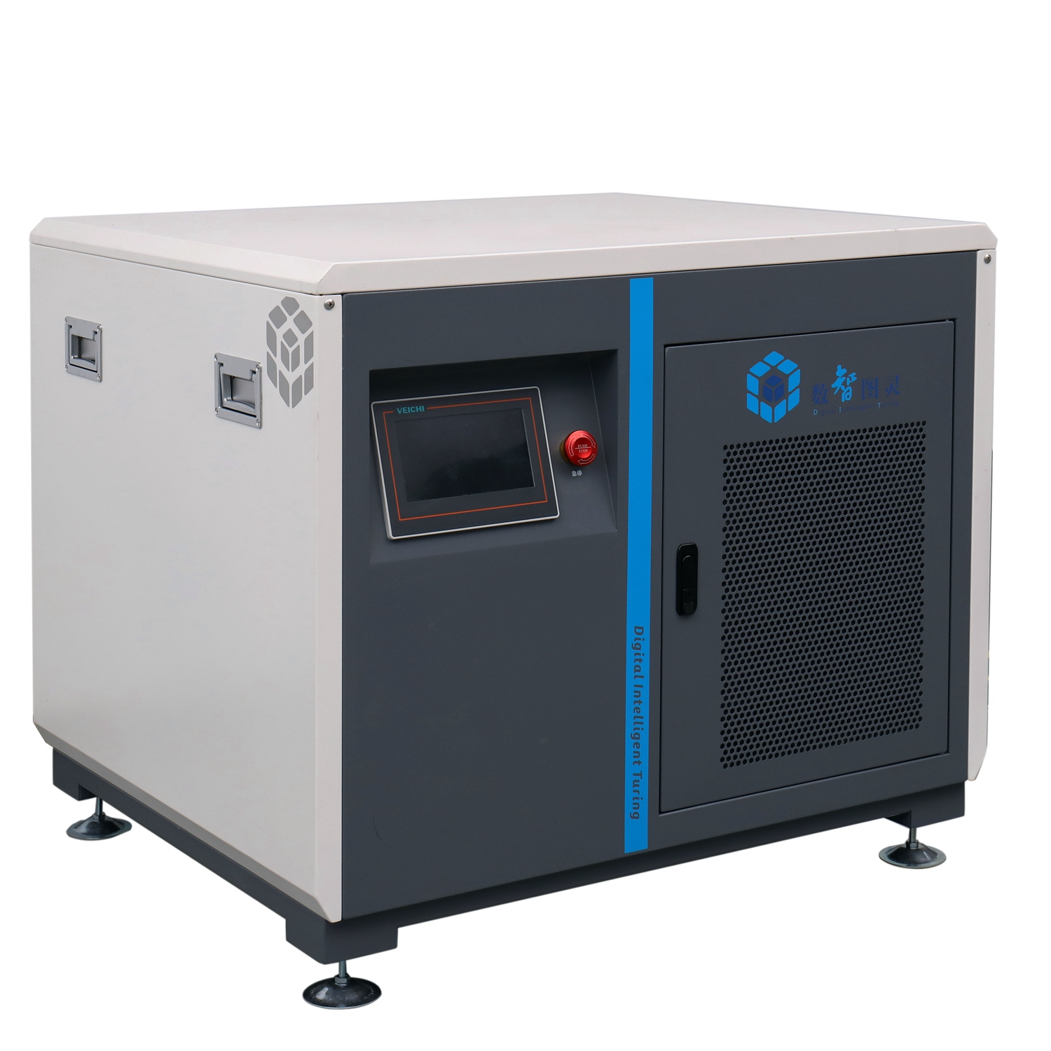
Software cannot fix mechanical limitations. The best PID algorithm in the world fails if the hardware cannot respond appropriately. Evaluating machine capabilities ensures your control loop functions as designed.
Turndown ratio defines a machine's operational flexibility. It represents the range between maximum output and minimum stable output. A blower’s ability to operate efficiently at partial loads remains the most critical evaluation metric for DO feedback integration.
If nighttime biological demand drops by 60%, your machine must be able to slow down by 60%. If it cannot reach deep turndown levels, you must vent excess air to the atmosphere. Venting air destroys the entire purpose of an efficiency upgrade.
Facilities typically choose between two primary compression methods. Each behaves differently under automated control.
Positive Displacement (PD) blowers provide linear control. They push a fixed volume of air per revolution. This makes them easy to map on a control curve. However, they suffer from lower baseline efficiency. They generate immense heat and extreme noise. These factors limit their suitability for advanced dynamic control in modern plants.
Conventional centrifugal blowers operate differently. They excel at base-loading. They generate high volumes of air smoothly. Unfortunately, they face severe aerodynamic limitations at reduced speeds. Slowing them down too much induces "surge." Surge occurs when system pressure exceeds the machine's discharge pressure. Air flows backward into the casing. This causes violent vibrations and mechanical failure.
Modern automation demands superior hardware. Evaluating a high-speed centrifugal blower is standard for DO control upgrades. These units utilize magnetic or air-foil bearings. They eliminate physical contact between the shaft and the housing.
This frictionless design unlocks extreme rotational speeds, often exceeding 20,000 RPM. They offer incredibly wide turndown ratios. They deliver near-instantaneous response times to VFD changes. More importantly, they maintain flat efficiency curves across highly variable operating ranges. You get maximum energy savings whether running at 100% or 45% capacity.
Technology Type | Turndown Capability | Efficiency at Partial Load | DO Loop Suitability |
|---|---|---|---|
Positive Displacement (Lobe) | Good (Linear) | Low to Moderate | Fair (Limited by baseline inefficiency) |
Conventional Centrifugal | Poor (Surge risks) | Moderate | Fair (Better for base-loading) |
High-Speed Centrifugal (Turbo) | Excellent (Wide range) | Very High | Optimal (Instant response, high efficiency) |
Integrating biology, electronics, and heavy machinery introduces specific risks. Recognizing these pitfalls during the design phase prevents costly operational failures later.
Wastewater contains grease, grit, and sticky biological matter. This harsh environment aggressively attacks submerged instrumentation. Sensor fouling ruins data integrity. If a dirty lens reads 0.5 mg/L when the actual basin sits at 2.5 mg/L, the PLC will force the equipment to maximum speed.
Inaccurate readings lead to erratic machine behavior. You must require self-cleaning optical sensors equipped with automated air or water blasts. Furthermore, plant operators must enforce strict calibration schedules. Trusting bad data destroys efficiency.
The PID loop requires masterful tuning. If the controller is poorly tuned, the system will continuously overcorrect. We call this phenomenon "hunting."
When hunting occurs, the machine ramps up aggressively to fix a low DO reading. It overshoots the target. The PLC panics and slams the VFD down to minimum speed. DO plummets. The cycle repeats endlessly. This wastes immense energy. It also degrades motor lifespans and wears out electrical components. You need automation engineers to tune the proportional and integral bands to ensure smooth, gradual speed transitions.
You cannot ignore the laws of biology. A fundamental delay exists between injecting air and seeing dissolved oxygen levels rise. Air bubbles take time to rise through the water column. Oxygen takes time to dissolve into a liquid state. Bacteria take time to consume it.
Control logic must acknowledge this biological delay. Operators must account for basin retention time. If the PLC expects instant results, it will command too much air. Adding predictive algorithms prevents the system from over-aerating while waiting for the biology to catch up.
Procuring the right equipment requires a structured approach. You cannot purchase hardware based solely on peak capacity. You must audit your entire infrastructure to ensure compatibility.
Assess your existing SCADA infrastructure before selecting new machinery. Can your current software handle high-speed data packets? Evaluate your current VFD capabilities. Finally, inspect your diffuser grids. If your fine-bubble diffusers suffer from severe calcium scaling, new equipment will struggle against massive backpressure. Clean or replace old diffusers first.
Demand transparency from original equipment manufacturers (OEMs). Use the following criteria to evaluate potential vendors:
Verified performance curves: Does the manufacturer provide verified performance curves at partial loads, or only at 100% capacity?
Native integration: Does the equipment package include native PLC integration for common industrial protocols like Modbus TCP or Ethernet/IP?
Surge protection: What are the documented mechanical and software surge protection mechanisms during sudden DO drop-offs?
Do not guess your system parameters. Conduct a comprehensive airflow demand study. Measure your minimum, average, and peak biological loads over several weeks. Include diurnal variations and seasonal shifts.
Use this data to size the equipment specifically for the optimal DO control range. You want your machine running in its highest efficiency sweet spot during your average daily load, with enough headroom for peaks and enough turndown for nighttime lulls.
DO feedback control offers massive operational advantages. It shifts facilities away from static, wasteful practices. However, it is not just a software upgrade. It requires a highly engineered mechanical pairing. You must match smart sensors with a responsive, variable-speed machine to realize true operational returns.
Prioritize your equipment evaluations based on verifiable turndown efficiency. Demand robust control-system integration from your vendors. Ensure your mechanical hardware can keep pace with rapid biological data changes. When you combine accurate optical sensors, properly tuned PID logic, and advanced high-speed compression, you achieve unparalleled process stability and energy conservation.
A: Sometimes, by adding a VFD. However, older motors often lack proper cooling and may overheat at low speeds. Additionally, the original aerodynamic design may not support a wide turndown range. Slowing down conventional models too much often induces destructive surging. A complete replacement usually yields better reliability and efficiency.
A: Optical DO sensors typically require manual wiping and sensor cap inspections every 3–6 months. They utilize luminescent technology, making them robust. Older galvanic sensors require much more frequent calibration, electrolyte fluid changes, and delicate membrane replacements to maintain accuracy.
A: They utilize frictionless bearings and integrated VFDs. This design allows them to rapidly and efficiently adjust rotational speeds in direct response to granular DO fluctuations. They offer massive turndown ratios without mechanical degradation, perfectly matching the erratic nature of biological oxygen demand.


