
- All
- Product Name
- Product Keyword
- Product Model
- Product Summary
- Product Description
- Multi Field Search
Please Choose Your Language
Views: 0 Author: Site Editor Publish Time: 2026-10-26 Origin: Site


Even the most efficient centrifugal blower suffers premature wear or catastrophic failure if you design its discharge piping poorly. Engineering teams often treat industrial air systems as entirely static networks. They frequently ignore the dynamic, invisible forces of high-velocity airflow, thermal expansion, and acoustic pulsation. This dangerous oversight transfers massive mechanical stress directly back to the rotating equipment. Such practices distort casings, destroy expensive bearings, and void manufacturer warranties rapidly. You must design discharge piping to manage these dynamic forces effectively from day one. We wrote this technical guide to give facility managers and engineers a clear decision-stage framework. You will learn how to evaluate and specify proper discharge supports for your systems. We will show you how to integrate flexible connections safely without introducing thrust risks. You will also discover how to select critical valve arrays to maintain high operational efficiency.
Support systems dictate equipment lifespan: Unmanaged thermal expansion and pipe weight transfer direct mechanical stress to the blower casing, distorting clearances.
Connections require thrust management: Flexible connectors isolate vibration but introduce thrust loads; control rods are non-negotiable in high-pressure applications.
Valve selection impacts efficiency: Improperly sized check or isolation valves introduce severe pressure drops, artificially raising the operating cost of centrifugal blowers.
Code compliance minimizes risk: Adhering to ASME B31.3 and MSS standards for supports and piping ensures structural integrity under dynamic loads.
Connecting rigid piping directly to rotating equipment transfers massive structural loads. This critical mistake leads directly to premature bearing failure and severe casing distortion. When you bolt a rigid steel pipe straight to a machine, thermal growth acts as a powerful lever. It pushes against the casing continuously during operation. This pressure shifts internal rotors off their precise centerlines. The resulting friction causes impellers to rub against the housing, leading to catastrophic internal damage. Manufacturers typically void warranties immediately when they discover direct rigid connections. Your piping design must decouple the machine from the surrounding building structure entirely.
You need clearly defined success criteria for any modern discharge system. First, ensure zero mechanical load transfers to the discharge flange. The piping network must support its own weight completely independently. Second, you must achieve complete vibration isolation. The blower skid and the facility floor should never share resonant frequencies. Finally, design the piping layout to maintain minimal frictional pressure drop. Every sharp elbow and undersized valve consumes valuable electrical energy. Reducing these drops keeps overall operational efficiency remarkably high.
Let us examine the real-world operational impact. You might save capital initially by skipping engineered pipe supports or premium isolation valves. However, this artificial savings vanishes quickly during a mechanical failure. Imagine a severe flange shear event damaging a premium single-stage turbo blower. The replacement parts alone cost thousands of dollars. Furthermore, the lost production time destroys plant profitability for weeks. Quality engineering prevents these expensive disruptions entirely. Proper design guarantees the equipment reaches its maximum engineered lifespan. You avoid sudden breakdowns and maintain steady production schedules year after year.
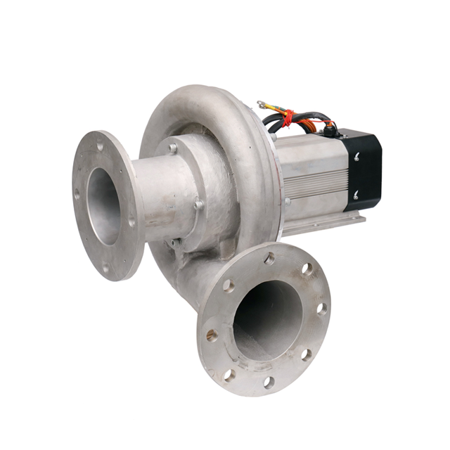
Engineers must understand the crucial difference between static and dynamic loads. Static load management involves supporting constant dead weight. This includes the massive steel pipes themselves, heavy isolation valves, and the compressed air volume inside. Dynamic forces require a completely different mathematical approach. You must manage continuous vibration, acoustic pulsations, and sudden startup surges. High-speed centrifugal blowers generate intense dynamic forces during standard operation. These forces multiply exponentially during surge conditions or emergency stops.
Let us thoroughly review the primary support categories available to engineers:
Base Supports & Saddles: These devices work best for long horizontal piping runs. You should equip them constantly with low-friction slide plates. PTFE or Teflon pads work exceptionally well here. They allow the heavy pipe to slide smoothly during thermal growth. This sliding motion prevents binding and sudden structural snapping.
Clamps & Clevis Hangers: We use these extensively for suspended overhead lines. You must evaluate them carefully for lateral sway. They can easily transmit unwanted vibration directly into overhead building structures. You often need diagonal sway braces to stabilize these hangers properly.
Spring Supports: These are absolutely essential for vertical piping runs. Thermal expansion often causes significant upward or downward movement in vertical spaces. Rigid supports would buckle under this immense pressure. Spring supports absorb this gradual movement safely. They maintain a constant supporting force regardless of pipe position.
Contractors must follow strict evaluation dimensions during installation. Require them to size and space all supports according to ASME B31.3 Process Piping guidelines. They must also strictly adhere to MSS SP-58 standard practices. Proper code compliance prevents dangerous flow shear. It also stops long-term structural fatigue in your pressurized system. Do not let installers guess support spacing on the fly. Demand stamped engineering calculations for every critical pipe run.
Mechanical isolation plays a massive role in system longevity. You must install a highly engineered flexible joint immediately downstream of the discharge flange. This critical component decouples the entire piping network from machine vibration. If you skip this step, vibration will eventually fracture pipe welds. It will also destroy concrete pipe anchors over time.
Material selection dictates how well the joint performs in the field:
Elastomeric/Rubber: These joints remain highly cost-effective and provide excellent acoustic dampening. However, they face strict limits regarding maximum discharge temperatures. Standard EPDM rubber degrades quickly above 250 degrees Fahrenheit. You must check operating temperatures before specifying rubber joints.
Corrugated Stainless Steel: You need these joints for high-heat compression cycles. They suit any heavy-duty industrial centrifugal blower perfectly. They handle extreme temperatures easily. Just remember they offer significantly less acoustic dampening than thick rubber joints.
You face serious implementation risks regarding internal thrust forces. Flexible joints act exactly like hydraulic cylinders when placed under pressure. They want to expand outwards violently. If you do not install properly tensioned limit rods, the joint over-extends. This over-extension transfers the entire internal thrust load directly back onto the machine flange. This massive force can easily shear the mounting bolts. Always specify robust control rods for these connections. Ensure maintenance teams never remove these rods during active operation.
Your valve choices dictate overall system performance and long-term reliability. Choosing the wrong valve type ruins system efficiency quickly.
Check valves prevent the dangerous reverse rotation of the machine. This protection matters greatly when you power the unit down. It is also critical in parallel equipment configurations. Dual-plate or wafer style check valves work best for air systems. They minimize internal pressure drop significantly compared to traditional swing checks. You must evaluate internal disc flutter based on minimum flow velocities. Too much flutter destroys the valve springs rapidly. Specify valves designed specifically for compressible gases.
Isolation valves separate the machine from the main pressurized process line. You need them for safe lockout-tagout maintenance procedures. Butterfly valves serve as the industry standard here. They offer a compact low profile and cost less than gate valves. However, high-temperature discharge might demand high-performance variants. Metal-seated triple-offset butterfly valves handle extreme heat beautifully. They provide a bubble-tight seal even at 400 degrees Fahrenheit. Always check your peak operating temperatures before ordering isolation valves.
These specific valves protect the casing and piping from dangerous overpressure events. A downstream blockage can destroy a system instantly. You must size these relief valves correctly. They must vent the absolute full capacity of the unit. They should do this while maintaining the maximum safe operating pressure. Place them as close to the machine as possible. Never install an isolation valve between the machine and its relief valve.
Discharge Valve Selection and Application Summary
Valve Category | Primary Function | Best Practice Selection |
|---|---|---|
Check Valves | Surge & Backflow Prevention | Dual-plate or wafer style |
Isolation Valves | Maintenance & Control | Butterfly valves (metal-seated for high heat) |
Pressure Relief | Overpressure Protection | Spring-loaded, full capacity venting |
You will likely encounter acoustic vibration and flow shear eventually. You must learn to identify the root cause quickly and accurately. System vibration might be purely mechanical. Coupling misalignment or unbalanced rotors cause severe mechanical shaking. However, the problem is often completely aerodynamic. Flow shear causes immense internal turbulence. Abrupt piping transitions usually create this shear. Poorly placed valves also disrupt smooth laminar flow. You can use vibration spectrum analysis to pinpoint the exact cause.
We highly recommend performing routine flange loading audits. Try the unbolting method post-installation to verify proper alignment. Unbolt the flexible connection from the machine flange carefully. If the pipe springs away or misaligns laterally, you have severe residual tension. You must adjust the pipe supports until the flanges align perfectly without applied force. You want absolute zero residual tension on the equipment casing. This simple test prevents years of premature bearing failures.
Straight run requirements remain completely non-negotiable. You must maintain three to five pipe diameters of straight, unobstructed piping. Place this straight section immediately downstream of the machine. Do this before you install any elbows, tees, or valves. This straight run stabilizes the highly turbulent flow exiting the machine. It prevents severe vibration and protects delicate valve internal components. Ignoring this rule guarantees noisy operation and rapid equipment degradation.
Reliable discharge piping requires a thoroughly holistic engineering approach. You must ensure your mechanical supports carry the full dead weight. Your flexible joints must absorb all operational vibration perfectly. Finally, your valves must protect the process from surges and backflow reliably. When these three vital elements work together, your system runs flawlessly for decades.
You should take immediate next-step actions today. Start by auditing your existing P&ID drawings for straight-run compliance. Calculate your anticipated thermal expansion based on peak discharge temperatures. Consult with structural mechanical engineers to verify your support load calculations thoroughly. Do all of this critical legwork before procuring new valves and expansion joints. Proactive engineering always outperforms reactive maintenance.
A: No. Hard-piping transfers structural loads and thermal expansion directly to the blower casing. This dangerous practice leads to rapid bearing and alignment failures. It also voids most manufacturer warranties. Always use an engineered flexible connection to decouple the machine.
A: Typically, you should place it 3 to 5 pipe diameters downstream. This straight run ensures turbulent air from the discharge flange has stabilized completely. Proper flow stabilization prevents severe valve chatter and premature wear of the internal plates.
A: Not always. Discharge piping is often increased in diameter. Engineers use an eccentric or concentric expander immediately after the flexible connection. This diameter increase reduces air velocity and minimizes frictional pressure drop across long pipe runs.


