
- All
- Product Name
- Product Keyword
- Product Model
- Product Summary
- Product Description
- Multi Field Search
Please Choose Your Language
Views: 0 Author: Site Editor Publish Time: 2026-09-29 Origin: Site


Specifying a High-Speed Centrifugal Blower represents a high-stakes capital expenditure decision. Underperformance severely disrupts factory production schedules and critical processes. Conversely, over-engineering artificially inflates daily operational expenses for years. Engineers frequently face intense frustration during commissioning phases. Field performance often deviates wildly from standard factory test curves. Misunderstood environmental variables usually cause these disruptive efficiency discrepancies. Improper system control integration plays an equally damaging role.
We promise a strictly technical, evidence-based breakdown below. You will learn the exact mechanical variables dictating system pressure and volumetric airflow. We provide a clear, actionable framework for evaluating complex equipment. You can effectively shortlist the right industrial blower using these proven engineering principles. Proper specification requires deep alignment between environmental realities and mechanical limits.
Blower performance is not static; it is dictated by the intersection of the blower’s performance curve and the specific system resistance curve.
Impeller design (backward-inclined vs. radial) and rotational speed are the primary mechanical drivers of centrifugal blower pressure and volumetric flow.
Environmental variables—specifically air density, elevation, and temperature—can degrade expected airflow by up to 20% if not calculated during the specification phase.
Choosing the right control mechanism (VFDs vs. Inlet Guide Vanes) is critical for maintaining efficiency at partial loads without inducing surge.
Engineers must first grasp the inverse relationship governing pneumatic performance. The performance curve visually maps this fundamental mechanical truth. As volumetric output increases, static pressure capabilities typically drop. A machine simply cannot deliver maximum flow and maximum pressure simultaneously. You must carefully balance these two competing metrics. Designing a system requires knowing exactly where your requirements fall on this curve. Achieving optimal centrifugal blower airflow depends entirely on balancing this inverse relationship.
System resistance forms your primary business problem. Think about friction occurring inside your facility. Ductwork, piping, diffusers, and filter media all create restrictive friction. The machine only delivers the exact airflow your system resistance allows. Airflow does not push itself through a pipe. Instead, the machine generates pressure to overcome system friction. When resistance increases, volumetric flow decreases accordingly. A heavily clogged filter shifts your performance dramatically leftward along the curve.
You must clearly define your target operating point. This intersection marks your ultimate success criteria. The operating point sits exactly where the machine performance curve crosses your system resistance curve. We always aim to place this intersection precisely at the Best Efficiency Point (BEP). Operating near the BEP maximizes energy conversion. It minimizes destructive vibration. It extends bearing life significantly. Deviating far from the BEP invites mechanical instability and massive energy waste.
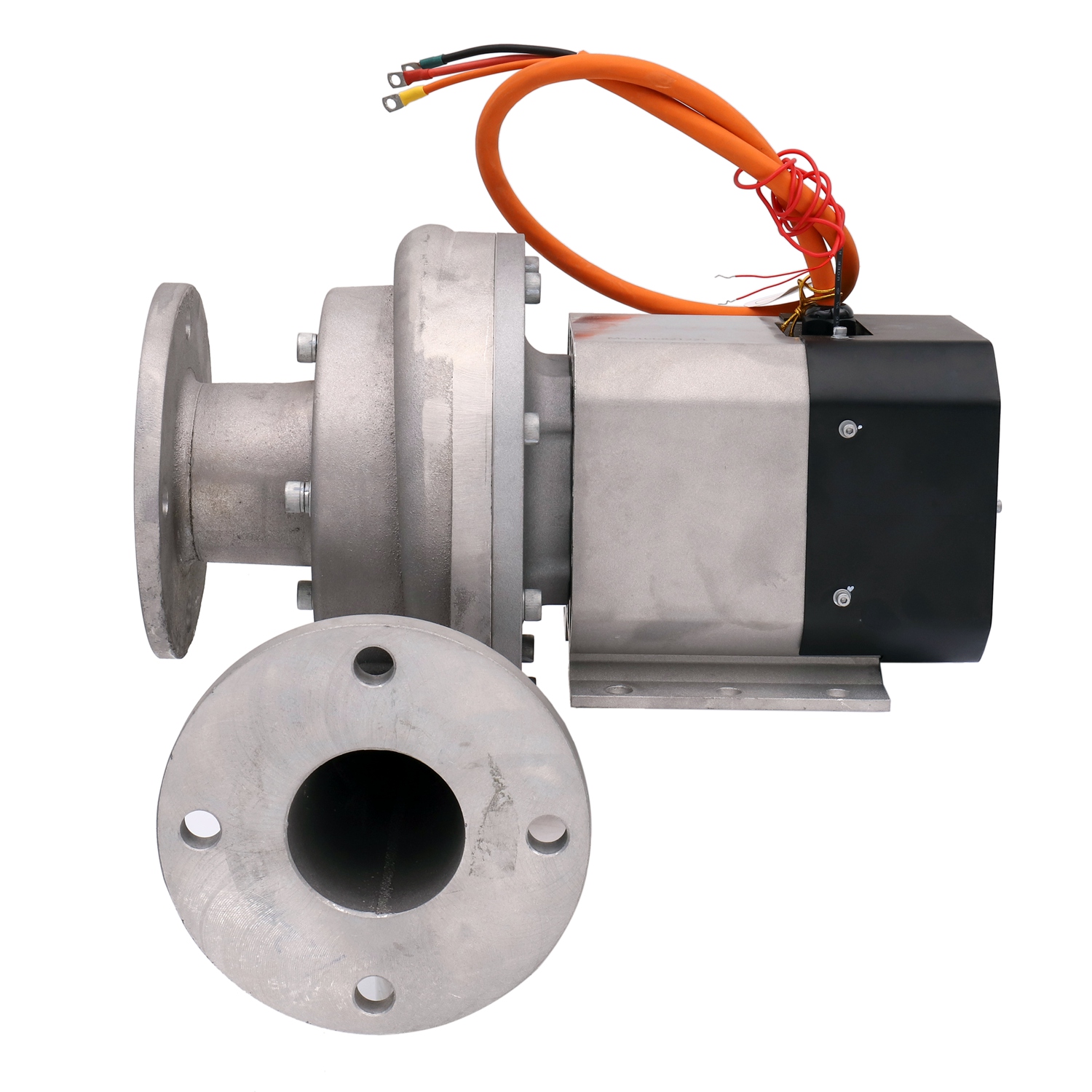
Impeller geometry dictates internal aerodynamics. Manufacturers utilize backward-curved or backward-inclined blades for most modern high-speed designs. These blades offer exceptionally high aerodynamic efficiency. They also feature stable, non-overloading power characteristics. The motor will not draw excessive current if system resistance suddenly drops. These characteristics make backward-inclined designs the gold standard for mainstream evaluation lists.
Conversely, engineers sometimes select radial blades for specialized applications. Radial impellers feature straight blades extending directly outward from the center hub. They offer lower overall aerodynamic efficiency. However, they resist wear exceptionally well. You often see radial designs used for a specialized high pressure blower handling heavy particulate loads. They prevent sticky dust from accumulating on the blade surfaces.
Engineers rely heavily on the Affinity Laws. These mathematical rules predict performance changes during speed adjustments. RPM scaling drastically alters pneumatic output. We must carefully calculate these changes before altering motor frequencies.
Volumetric flow changes proportionally directly to rotor speed.
Static pressure changes by the square of the speed ratio.
Power consumption changes by the cube of the speed ratio.
These laws reveal a severe implementation risk. Engineers sometimes try fixing pressure deficits simply by turning up the RPM. We strongly warn against this brute-force approach. Because you need to hit a specific centrifugal blower pressure, doubling your speed quadruples your pressure. However, it requires eight times the original motor power. This causes exponential energy consumption. It also introduces severe mechanical failure risks due to excessive shaft vibration.
Machines convert kinetic energy into static pressure. This complex fluid dynamic process relies heavily on the casing expansion profile. Air leaves the spinning impeller at extreme velocities. The volute casing gradually expands in cross-sectional area. This controlled expansion slows the air down. Physics dictates an immediate trade-off here. Decreasing air velocity directly increases static pressure.
Manufacturers must maintain exceptionally tight physical tolerances. The gap between the spinning impeller and the stationary inlet cone matters immensely. Wide gaps allow high-pressure air to bleed backward into the low-pressure inlet. This internal recirculation acts as a parasitic leak. It severely degrades aerodynamic efficiency. High-quality manufacturing prevents this internal leakage completely.
Physics dictate undeniable realities regarding environmental conditions. Centrifugal machines move a constant volume of air. However, they do not move a constant mass. Altitude and temperature drastically alter air density. We must address this specific phenomenon early during specification.
Imagine a machine operating in Denver during peak summer. The elevated altitude provides physically thinner air. The extreme summer heat reduces air density even further. The machine still moves the exact required cubic feet per minute (CFM). However, the less dense air contains significantly fewer gas molecules. The machine delivers much less physical mass. Consequently, it generates much lower static pressure. Failing to calculate these density corrections degrades expected field airflow by up to 20%.
Installation realities often destroy perfect laboratory test curves. We call this phenomenon the System Effect. Poor ducting design creates massive parasitic losses. Fluid dynamics demand smooth, uniform airflow entering the impeller eye.
Contractors sometimes install sharp elbows immediately before the inlet. They also place restrictive valves directly at the discharge flange. These poor piping configurations induce severe air turbulence. The turbulence violently disrupts aerodynamic lift inside the impeller. The machine suddenly underperforms its factory rating. Factory test curves assume perfectly straight ducting. You must account for these real-world layout compromises during your design phase.
Plants rarely operate at constant maximum demand. You need effective capacity control strategies for partial load cycles. Selecting the wrong control mechanism wastes massive amounts of electricity.
Capacity Control Strategy Comparison
| Control Strategy | Efficiency Level | Primary Advantage | Primary Risk / Disadvantage |
|---|---|---|---|
| Variable Frequency Drive (VFD) | Excellent | Scales power draw cubically with speed reduction. | Surge line crossing if RPM drops too low against high resistance. |
| Inlet Guide Vanes (IGV) | Good | Highly effective for constant-speed motors. | Mechanical complexity; moving parts require regular maintenance. |
| Discharge Throttling | Poor | Very cheap initial installation cost. | Acts as an artificial bottleneck; wastes massive energy. |
VFDs represent the most efficient method for scaling performance down. They electrically reduce motor rotational speed during low-demand cycles. The Affinity Laws dictate massive energy savings here. Reducing speed by 20% cuts power consumption by nearly 50%.
However, you must respect VFD turn-down limitations. Dropping RPM reduces pressure capabilities exponentially. If your system resistance remains high, low RPM operation becomes dangerous. The machine cannot overcome system friction. It crosses the surge line. Surge causes violent, destructive airflow reversals. You must map your low-speed operating points carefully.
Inlet Guide Vanes offer a highly viable alternative for constant-speed motors. These mechanical louvers sit directly in front of the impeller inlet. They physically pre-rotate the incoming air in the direction of impeller rotation.
This pre-rotation artificially alters the native blower curve. It significantly reduces power draw when full volumetric flow isn't required. IGVs provide excellent aerodynamic turndown capabilities. They help prevent surge better than simple throttling mechanisms. You trade some electrical efficiency for superior mechanical stability.
We must strongly caution against basic discharge throttling. Contractors often install a simple butterfly valve at the discharge. Closing the valve restricts airflow to meet lower demand.
This method proves highly inefficient. It acts as an artificial mechanical bottleneck. The motor continues working at full speed. It wastes massive amounts of electrical energy pushing against a closed valve. You should strictly avoid discharge dampers in modern, efficiency-conscious manufacturing facilities. They solve short-term budget constraints but destroy long-term operational budgets.
You must accurately define your true duty point first. Calculate your required volumetric flow and static pressure rigorously. Never base these calculations on perfect, pristine laboratory conditions. You must evaluate worst-case environmental scenarios.
Calculate air density using the highest expected summer temperatures. Account for maximum facility altitude. Determine system resistance assuming the dirtiest allowable filter state. Designing for these worst-case parameters ensures reliable continuous production. The machine will easily handle standard daily operations if it clears your worst-case thresholds.
Engineers often fall into a dangerous psychological trap. They arbitrarily add a 15-20% safety margin to their pressure requirements. They fear undersizing the equipment. We strongly caution against this widespread practice.
Arbitrary oversizing drives massive energy waste. An oversized machine operates far to the left of its Best Efficiency Point. It approaches the surge line dangerously. This causes mechanical instability and intense vibration. It also dramatically shortens bearing life. You must trust your worst-case mathematical calculations. Do not pile arbitrary safety margins on top of rigorous engineering math.
You must look far beyond the initial purchase price. The evaluation matrix must heavily weight wire-to-air efficiency. This metric measures how perfectly electrical power translates into pneumatic power. Even a 2% efficiency gain saves tens of thousands of dollars over a decade.
Furthermore, prioritize maintenance intervals heavily. Review the required bearing replacement schedules. Analyze the cooling system complexity. Complex machines require expensive specialized labor. Simple, robust designs keep facilities running predictably. Make your final selection based on long-term mechanical reliability rather than slight upfront discounts.
Predictable performance requires rigorous engineering discipline. You must firmly align mechanical machine specifications with your unique environmental conditions. System resistance dictates exactly what volumetric output your process receives. Remember, air density fluctuations drastically degrade pressure capabilities if left uncalculated. Avoid arbitrary safety margins. They only induce dangerous surge conditions and waste electricity.
We highly recommend taking an actionable next step. Consult directly with an experienced application engineer before requesting a final commercial quote. Ask them to run a custom performance curve analysis. Ensure they plot this curve against your specific facility elevation, maximum summer temperature, and peak system resistance. This rigorous pre-purchase step guarantees your final installation operates exactly as designed.
A: Your system resistance likely increased beyond the initial design parameters. Dirty filter media represents the most common culprit. It forces the machine to slide leftward on its performance curve, dropping volumetric flow. Additionally, unexpected extreme heat lowers air density, reducing the machine's ability to move adequate mass flow.
A: No. Performance changes dramatically according to the Affinity Laws. Static pressure drops by the square of the speed reduction. If you reduce motor speed by half using a VFD, your static pressure capability drops to exactly one-quarter of its original maximum rating. You must calculate this carefully to avoid surge.
A: Base your evaluation strictly on process requirements. Choose a PD blower if your process demands a constant, unwavering volume of air despite wildly fluctuating system pressures. Choose a centrifugal machine if your process requires variable airflow volumes operating against a relatively constant system pressure environment.


